Reflection 3
Salam 1 Malaysia....
This week..... I want to talk about The Ultiboard. In my opinion,I think Ultiboard is the great software because it can make our circuit become 3D. So, from this 3D view, I can understand this software clearly.This software can view the shape our component. For example, we can see clearly what is the shape capacitor,resistance,LED,and so on.This software Ultiboard has a relationship with the software Multisim,because before I used Ultiboard, I must designed our circuit using Multisim. Only then i can transfer my schematic draft to ultiboard.
Do you know what is mean by Ultiboard??
From my research...Ultiboard is used to design printed circuit board,perform certain basic mechanical CAD operation and prepare them for manufacturing,and also provides automates parts placement and layout.

*The menus and toolbar give you access to the ultiboard commands
This week I have test on Ultiboard..because last week I have already learn how to used the Ultiboard software.This week En.Ridzwan want to test us,how far we understand to used the ultiboard Picture below showing the question for my test this week....

This my test for this week...
After I received my test,I designed my task in the Multisim software....

This is my circuit in multisim before I transfer it to the Ultiboard..After I have done designed my circuit in multisim,the next step is to transfer to the Ultiboard...

But En Ridzwan want us to build the new board outline,i mean with different shape board outline.So,I have designed my own board line with my own creativity...

Now...this is my new board outline..before I arrange my components part I will tell you how to make the board outline or change the shape of my circuit board:
1.Firstly,you must click layer and choose board outline..
2.Then,you right click on your board line and go to shape and choose the shape that you like for your board outline...
3.After you have finished designed your board outline...you can delete your original board outline...
Next step is,I want to arrange my component in my new outboard line.....

Now,I have done arrange my component in my board....Now,i want to tell you how to arrange our component:
1.you must choose copper top at your layer....It want to make sure that your board does not moving while you want to arrange your components...
2.Then,you click the Enable selecting parts at your tools box,after that, you can arrange your component with your creativity that you like...
After that,En Ridhwan want my some component at the bottom of my board...so to do that we must ...
1.Select the component that you want to bring to the bottom of your board outline...
2.Then,double click at your selected component one by one...and choose position and selected your board side..
Next steps is,you auto route your ultiboard....auto route is wanted to make our circuit connection become more tidy....
This circuit is not auto route yet.....

This circuit was done autoroute...after autoroute,we can change the thickness your route layer...to edit the thickness of route layer:
1.you close the enable selecting parts button and open the enable selecting traces...
2.Then,you select all the traces in your board outline..and double clik on your traces and adjust the thickness of your route layer...with the thickness that you like....
After that,you can view your circuit in 3D view.....
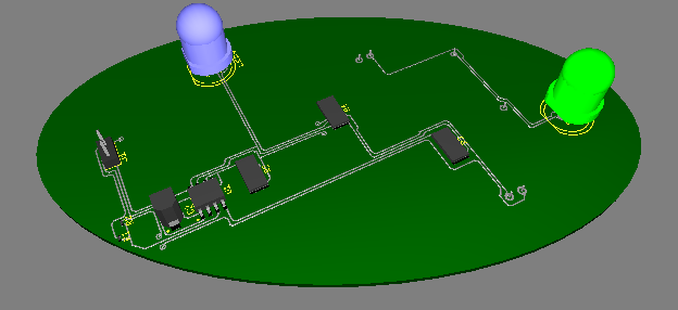
This picture show us the component at the top of our board line

This picture show us the component at the bottom of the board..
In my conclusiom,I think the Ultiboard software is a user friendly.Many people can learn how to used or operate this software...That's all from I for this week....Tq.....


